Research reports
In order to keep producing ground-breaking science with ALMA in the coming decade and beyond, timely updates of its hardware and software are necessary. Here, the different projects and studies which constitute the contribution of East Asia to the ALMA Development Program are summarized. This includes the production of Band 1 receivers, the development of Band 2 receivers optics, and of the ACA spectrometer, and different hardware and software studies towards the implementation of the ALMA Development Roadmap and additional opportunities.
The ALMA Band 1 receiver will cover the 35-50 GHz (up to 52 GHz as best effort) frequency range, which represent the lowest frequencies in ALMA. The receiver was developed by an international consortium led by ASIAA (Taiwan), in collaboration with NAOJ, NRAO (U.S.), HIA (Canada) and University of Chile. Production of 73 receiver units is being carried out in Taiwan, led by ASIAA, in collaboration with NAOJ. NAOJ contributes the design and production of warm lenses and corrugated horns in collaboration with University of Chile and ASIAA.
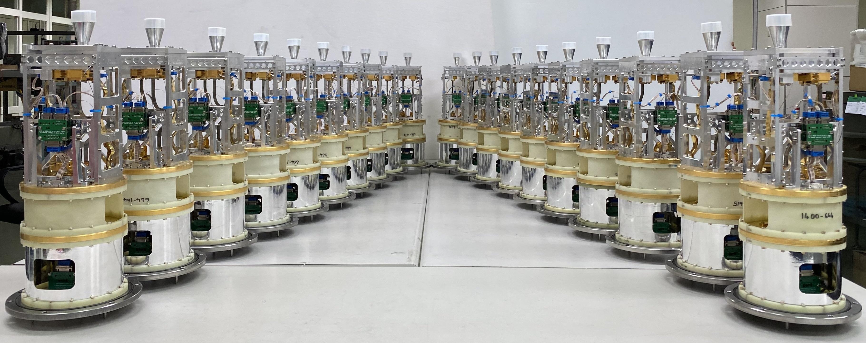
ALMA Band 1 Receiver. Credit: ASIAA
The ALMA Band 2 receiver will cover the 67-116 GHz observation frequency range and it has been developed by a consortium led by ESO and with contributions from NAOJ, INAF (Italy), University of Chile, University of Manchester (UK), Chalmers University (Sweden) and other institutes in Europe. This project has entered in the pre-production phase, led by ESO and with the contribution of optical components by NAOJ, to produce 6 full receiver cartridges before moving forward with the full production. NAOJ has contributed to the Band 2 receiver development with the design, fabrication, and testing of waveguide components (OMT and corrugated feed horn) and receiver optics based on a warm dielectric lens.
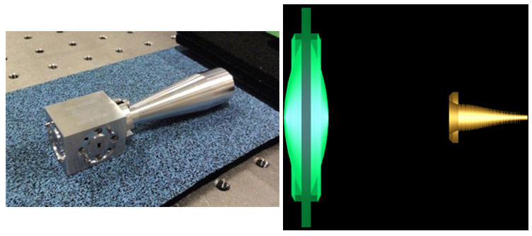
(Left) Band2 optics component. (Right) Band 2 optical design. Credit: NAOJ
The ACA Spectrometer is being developed to process the signals from the Total-Power Array with better linearity and signal-to-noise ratio and higher dynamic range, and will operate in parallel to the ACA Correlator. The ACA Spectrometer is based on GPU technology instead of the FPGA technology used in the ACA Correlator. The project is led by KASI, in collaboration with NAOJ. NAOJ has produced the full set of the ACA Spectrometer hardware consisting of GPU servers, Linux servers, and DRXP boards. The installation of the ACA Spectrometer hardware in the ALMA telescope will be in February 2021 followed by the corresponding commissioning activities in April-June 2021. (This schedule is subject to change depending on the evolution of the COVID-19 pandemic)
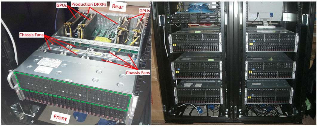
ACA Spectrometer hardware in the final stages of production.
(Left) Detail of one GPU server (Right) Full instrument. Credit: NAOJ
NAOJ developed an artificial calibration source based on microwave-photonics techniques. It is essential for ALMA to correct the individual difference of antennas/receivers. In particular, measurement of the polarization properties of each antenna is more complicated owing to multi-path propagation in the optics.
An arrangement of two wire grids, one that rotates about an axis perpendicular to the plane of the grid, can produce a highly linear polarization signal with polarization extinction ratio of better than 30 dB that is rotatable with a polarization angle. Measured polarization angle accuracy is better than 0.75-degrees. The artificial calibration signal complies with ITU regulations.
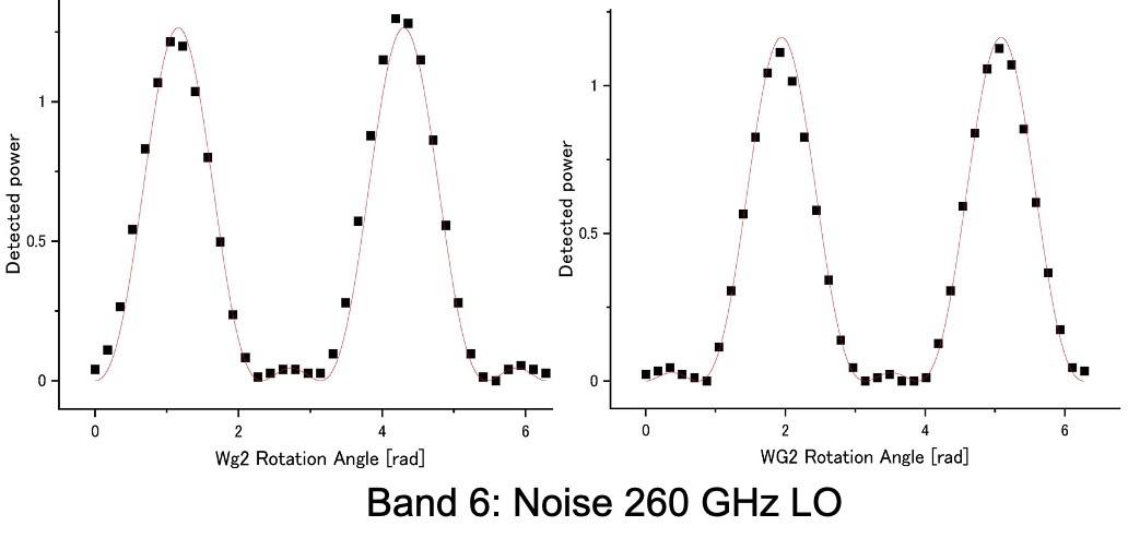
ALMA Band 6 signals from the Artificial Calibration Source. Credit: NAOJ
NAOJ has been studying possibilities of Archive development and receiver and photonic technologies to implement observations with wider bandwidth, better sensitivity, wider field of view, and longer baselines towards the next decade, as identified in the ALMA Development Roadmap.
NAOJ has studied and developed optics components in the wide RF range from 35 GHz to 1.5 THz such as dielectric lenses, corrugated horns, OMTs, which determine the receiver RF performance. We have established dielectric material characterization systems at the 67-116 GHz and 330-500 GHz bands for more accurate lens and anti-reflection coating design. The developed optical components can be characterized by a universal beam pattern measurement system covering 35 GHz-1.5 THz.

(Left) Dielectric material characterization system and its simulation. (Right) Beam measurement system.
Credit: NAOJ
NAOJ has been studying low-noise wideband receivers technologies for particular frequency bands. We have developed waveguide RF components and superconductor-insulator-superconductor (SIS) mixers targeting the 275-500 GHz frequency range (corresponding to the combined ALMA Band 7 and Band 8) and an IF bandwidth of 3-22 GHz for technology demonstration. Based on these developed components, a double sideband (DSB) receiver frontend in combination with a high-speed digitizer has been demonstrated with instantaneous bandwidth of 17 GHz and achieving quantum-limited low-noise performance across the RF range.
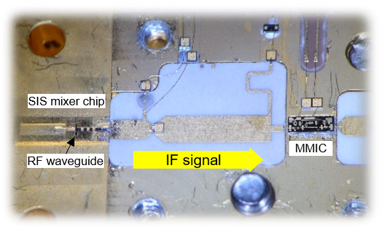
Microscopic photo of the wideband mixer. Credit: NAOJ
A multi-beam receiver frontend based on current technologies is challenging, because of the tight receiver technical specifications and predefined engineering constraints. At NAOJ, a new concept of planar integrated arrayed SIS receiver is being studied. The scheme is characterized by the adoption of silicon membrane-based waveguide probes, which allows a dramatic increase of integration level on superconducting monolithic microwave integrated circuits (MMICs). A 2 x 2 dual-polarization balanced SIS mixer array has been demonstrated with this scheme and assessed at ALMA Band 4 frequencies. This demonstration indicates the feasibility of multibeam receivers for ALMA application.
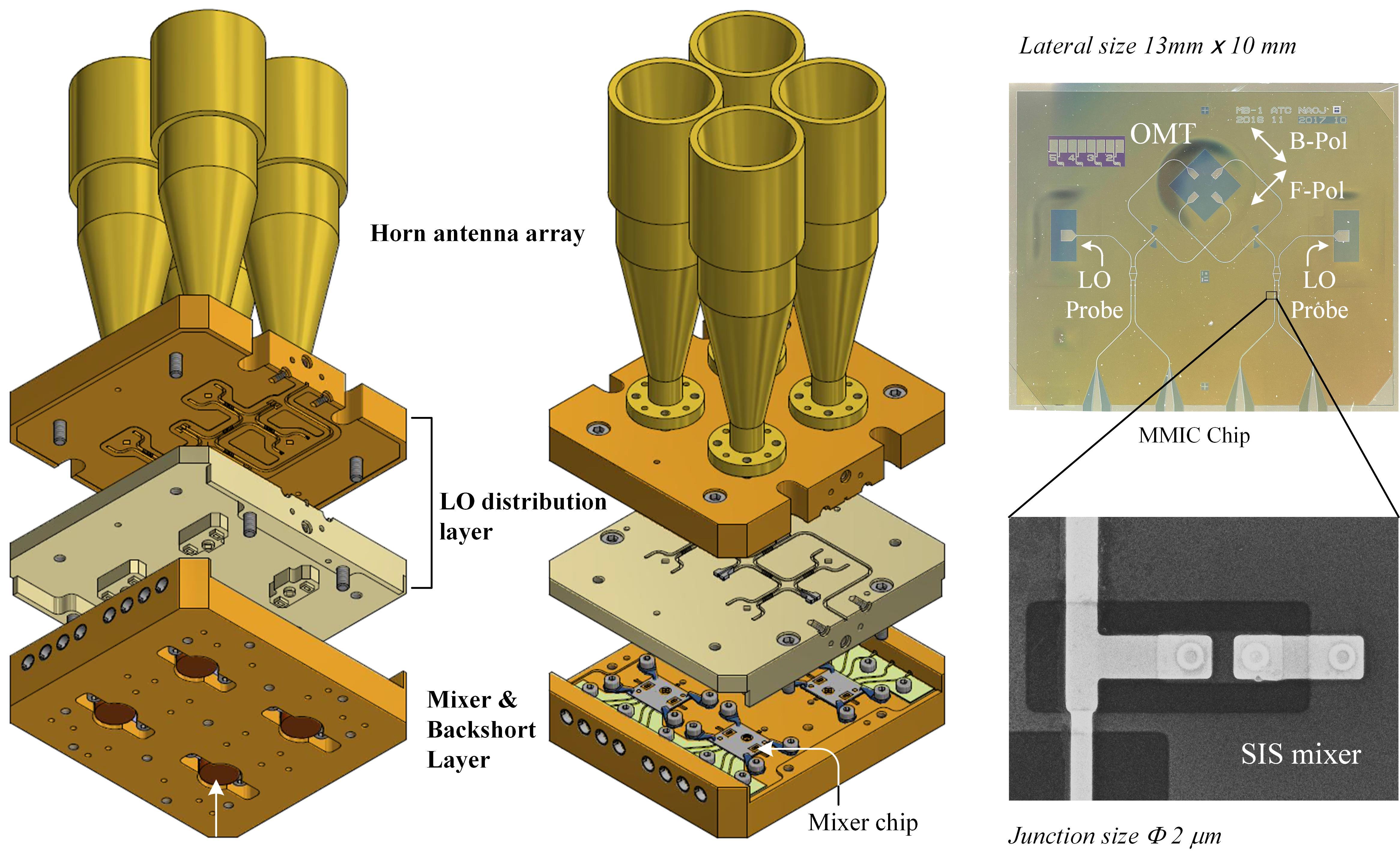
(Left) Mechanical model of the 2x2 multibeam mixer block.
(Right) Photo of a MMIC chip and a SEM image of the SIS mixers. Credit: NAOJ
NAOJ designed and produced the ALMA Band 10 receivers (RF: 787-950 GHz) and completed the delivery of 73 cartridges in 2014. NAOJ continues to target the improvement of the ALMA band 10 receiver performance. We recently focused on technology development in several directions: 1) lower noise temperature, 2) wider IF bandwidth mixer, and 2) sideband-separating (2SB) mixer. These developments are being proceeded independently but will be merged in the future.
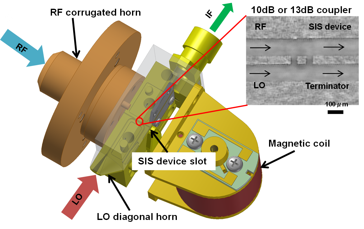
Schematic view of the terahertz SIS mixer. Credit: NAOJ
NAOJ has successfully produced high-quality SIS mixers for ALMA Band 4, 8, and 10 receivers. For future ALMA receiver upgrade, fabrication technologies have been developed in two different directions. The first is focused on the fabrication of SIS junctions with ultra-high current density, low sub-gap leakage and sub-micron size. These junctions are essential for the development of wideband receivers. The second direction is the development of silicon-based micromachining techniques, including microwave monolithic integrated superconducting circuits, THz waveguide structures, and quasi-optical components. This technology leads to a significant improvement in the receiver integration level and performance due to micrometer-range dimensional accuracy. These microfabrication technologies being established in NAOJ microfabrication facilities are fundamental in supporting ALMA receiver maintenance and future upgrades.
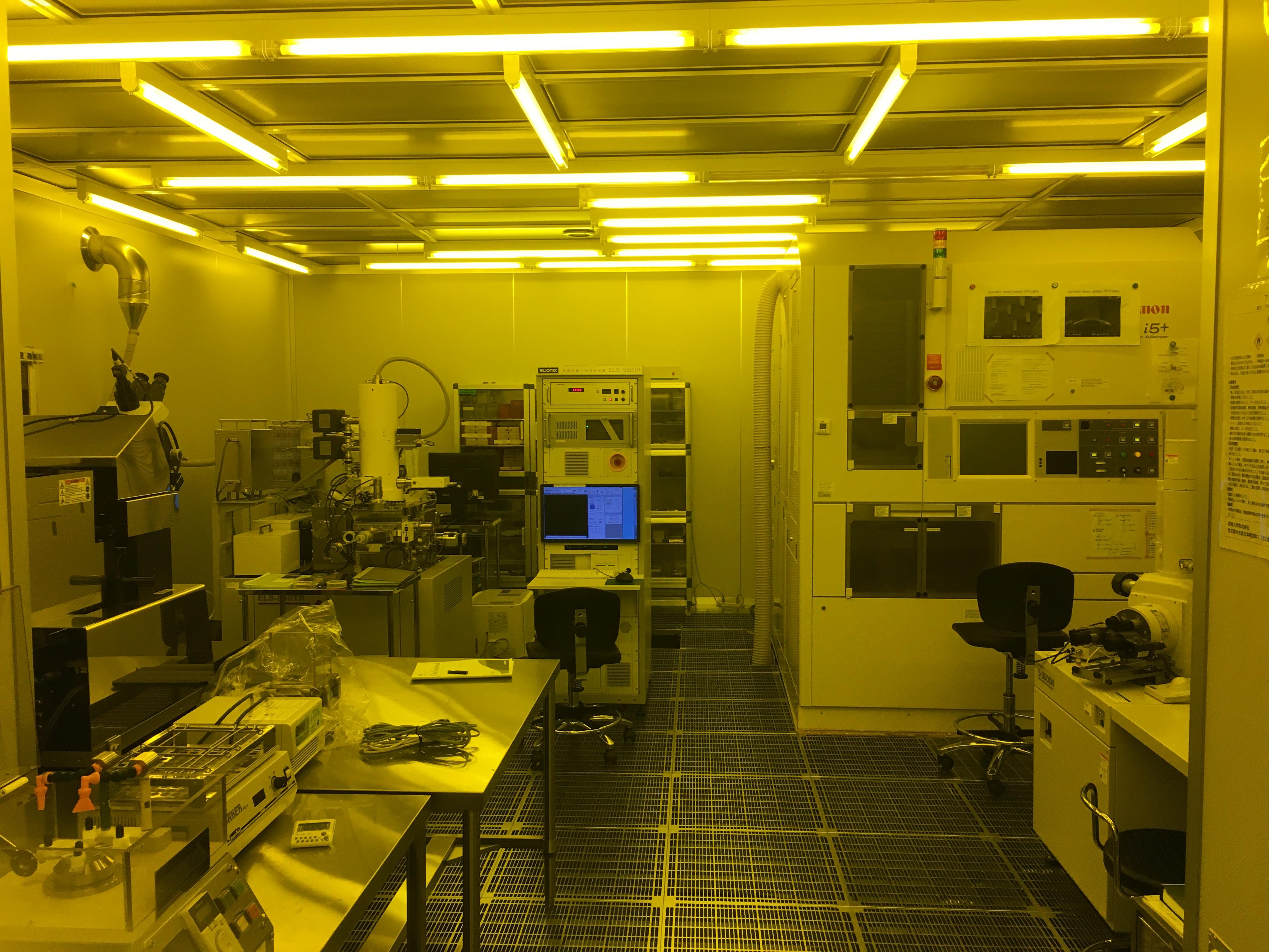
Microfabrication facilities in the clean room at the NAOJ Advanced Technology Center. Credit: NAOJ
NAOJ have been investigating the use of all-metal 3D printing for the fabrication of waveguide components in the lower frequency bands of ALMA. Recently, we have demonstrated the fabrication of a corrugated horn for the 35-50 GHz band, and its use at cryogenic temperatures as part of a band 1 prototype receiver, in collaboration with ASIAA. This activity paves the way towards the use of 3D printing for quick and cost-effective prototyping, or even for efficient mass production of components.

(Left) 3D-printed corrugated horn for the 35 - 50 GHz band. (Right) 3D Printer at the NAOJ Advanced Technology Center. Credit: NAOJ
We have developed a post-processing scheme transmission phase stabilizer to provide a highly stable microwave-photonics signal over a large broadband from microwave to terahertz frequencies using the same optical signal generation/transmission system. While transmitting signals through an optical cable, the transmission delay fluctuates and it suffers from chromatic dispersion that affects the distribution signal coherence. In the scheme, the measured phase of the round-tripped signal is acquired at time intervals at the optical transmitting port, and then the measured phase data are sent to the destination port for the transmission phase compensation. Theoretically, there is no upper frequency limit.
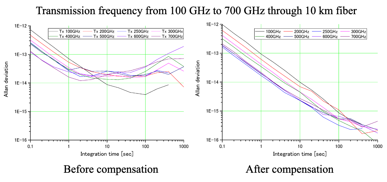
Signal transmission experiment through a 10-km optical fiber. Credit: NAOJ
Currently, NAOJ is performing three different software or computer related Development Studies. One of them is the development of the "Python module for Radio Interferometry Imaging with Sparse Modeling" (PRIISM). PRIISM is a new imaging tool for radio interferometry using the sparse modeling technique. PRIISM can be integrated and runs on Common Astronomy Software Applications (CASA), which is the standard data analysis software for ALMA. Several EA-ARC astronomers have already started using PRIISM for the scientific validation and also for their own science purposes.
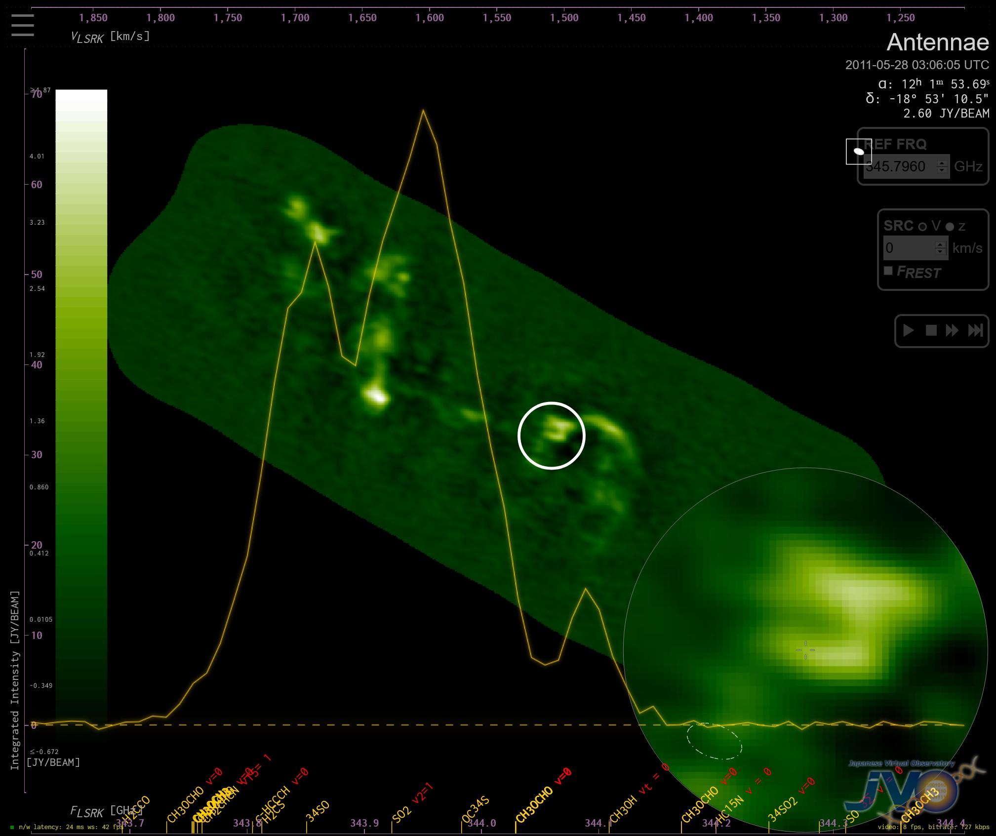
Screenshot of the ALMA FITS WebQL available on the Japanese Virtual Observatory. The integrated spectrum inside the white circle is overlayed on the image. The white circle area is enlarged and displayed at the lower right-hand side corner. Credit: NAOJ