|
The Future Large Millimeter and Submillimeter Array (LMSA/ALMA) Project and Technical Challenges |
|
Ryohei Kawabe, and LMSA working groups |
Abstract—The Japanese Large Millimeter and Submillimeter Array (LMSA) and US/Europe Atacama Large Millimeter Array (ALMA) are planned to be constructed at a very high and dry site in the northern Chile and to be operated at frequency range of 80 to 900 GHz from around the year of 2008. LMSA (or ALMA) will provide 0.01 arcsecond resolution and a very high sensitivity corresponding to a 70 m single dish. Its main targets include planetary system formation and galaxy formation/evolution. A big advance in the other researches (e.g., cosmology), is also expected. The Technical challenges to key instruments for such arrays are now performed; i.e., developments of high precision antenna, low-noise sub-millimeter mixers, high-power sub-millimeter LO sources, and very high-speed samplers and wideband spectro-correlators. The array projects and the technical challenges mainly by Japanese LMSA group are presented.
Index terms—submillimeter-wave astronomy, interferometer, submillimeter technologies
I. INTRODUCTION
A. Scientific Motivations of Large millimeter and Submillimeter Arrays
The observations of cool interstellar material, form which planets, stars, and galaxies are formed, in the millimeter and sub-millimeter wavelength ranges during the past 20 years have helped to elucidate the nature and evolution of interstellar matter in the Galaxy and external galaxies. The observations also revealed various exciting phenomena such as active outflows from and mass accretion onto newly formed stars, protoplanetary disks of dust of gas around young stars, and forming galaxies in the early universe [e.g., 1, 2]. These studies have led great progress in understanding the process of star and planet formation, the evolution of galaxies, and interstellar chemistry.
The Large Millimeter and Submillimeter Array (LMSA) project [3, 4] of the Japanese astronomical community entails the construction of an interferometer consisting of fifty 10m-class antennas and covering a frequency range from 80 GHz to 900 GHz. With a maximum baseline of 10 km, spatial resolution of 0.01 arcseccond could be achieved for the observations at 300 GHz. A similar kind of arrays, that is Atacama Large Millimeter Array (ALMA) is planned by US and Europe [5, 6]. A breakthrough is expected by combining these arrays into a more capable and powerful array. The unprecedented high sensitivity and high spatial resolution provided by LMSA/ALMA will open new era in millimeter and submillimeter astronomy. Such array will be powerful tool to explore a great variety of important problems in current astronomy, such as the formations of planetary systems, and formations of galaxies.
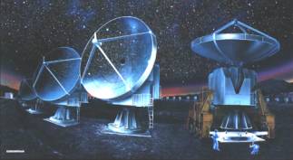
Fig. 1 Artist’s
impression of the Large Millimeter and Submillimeter Array (LMSA).
B. Specifications of LMSA/ALMA
The spatial resolution achieved is as high as 0.01 arcsecond even for not strong thermal emission such as dust and molecular emission. This is ~10 times finer than that achieved by the world’s largest optical/infrared telescopes such as Hubble Space Telescope or SUBARU 8.3m telescope. The maximum angular resolution corresponds to 1.4 AU (Astronomical Unit) at the distance of the Taurus dark cloud. The structure of plotoplanetary disk could be resolved and the central planet forming regions could be investigated by the high resolution.
The correcting area of each of LMSA/ALMA is about 8000-10000 m2, which corresponds to a 70 – 80 m single dish telescope. Each antenna for LMSA is planned to be equipped with very sensitive receivers using SIS (superconductor-insulator-superconductor) junction, one of superconducting tunnel junctions, which covering entire atmospheric windows in short-millimeter and submillimeter wavelengths shown in Fig. 2 [7]. The high sensitivity achieved by the large correcting area and sensitive receivers would allow us to search for forming galaxies located in the very early universe, which are covered by the dusty clouds and are, therefore, difficult to detect by optical and IR observations. The huge number of baselines (i.e., Fourier components; 1225 for LMSA) can be obtained at a time, and high-quality imaging can be performed even with so-called snap shot observations.
C. Key Instruments and Technical Challenges
The key instruments of LMSA/ALMA are 1) a high-precision submillimeter antenna, 2) low-noise millimeter and submillimeter receiver systems, 3) a very wideband spectro-correlator which can handle huge data set form a large number of antennas, and 4) radiometric system for atmospheric phase correction in order to achieve high spatial resolution by the active correction of the phase. The research and developments for these key items have been performed for more than two years in Japan. Recently, we started the design and construction of prototypes of such instruments as antenna, receivers, and correlators, as described in the following. The other topics related with this project are presented in two separate papers of this conference by Sakamoto et al. and Sekimoto et al.
Fig. 2 Best
atmospheric transmission measured at the 4800-m site of Pampa la Bola, Region
II, Chile (LMSA construction site), measured with a Fourier-transform
spectrometer [7] and important interstellar molecular and atomic lines in short
millimeter and sub-millimeter wavelengths. Note that super-terahertz atmospheric windows around 1, 1.3,
and 1.5 THz were clearly identified as well as the 650 and 850 GHz windows with
the peak transmission of > 60%. The receiver bands for LMSA were proposed in
order to cover the atmospheric sub-millimeter windows up to 900 GHz; receiver
bands are 80-140, 130-200, 200-310, 330-420, 390-500, 630-710, and 800-890 GHz.
II. Technical Challenges to Key Instruments
A. High Precision Sub-mm Antenna
The design of high-precision antenna for LMSA/ALMA should be performed with extreme care. This is because it is the first time to develop 10-m class antenna used for the exposed condition and because the replacing or upgrading of a number of high-precision antennas constructed once will be quite costly. The design of the element antennas is, therefore, one of the key issues in the research and development phase. For the Japanese design and development, we are now constructing a prototype antenna. We considered the antenna design from the following aspects; 1) good enough antenna performance for the observations up to 900 GHz, 2) easy assembling at the high site with an altitude of about 4800-5000 m and easy maintenance (or inspection) and high reliability under the environmental condition, 3) good matching with scientific requirements.
The specifications of the prototype antenna shown in Table 1 were determined as follow. The maximum surface error was set so that it is ~1/20 of the shortest observing wavelength (340 mm). The maximum pointing error was determined not to exceed 10% of the 7” field-of-view of the element antenna at 340 mm. Maximum slue rate was set to enable fast switching between two astronomical objects for the calibration of the array. This prototype antenna will be installed to Nobeyama Radio Observatory (NRO) in Jan. 1999. After testing at 100-345 GHz at NRO, this antenna will be moved to LMSA construction site in Chile for the evaluation at 345-810 GHz.
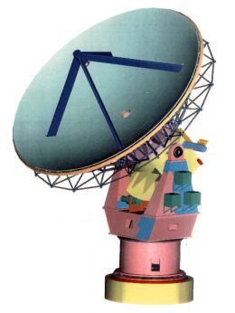
Fig. 3 Schematic
view of LMSA prototype antenna, in which sun shades covering its backing
structure were removed.
Table 1 Specifications of the LMSA prototype antenna
Diameter ~10 m
Frequency range 80–890 GHz
Surface error (rms) <25 mm
Pointing error (rms) <1.5 ”
(Night, wind velocity <7m s–1)
Phase stability (rms) <20 mm
Slue rate >3 deg. s–1
Receiver cabin >2 m x 2 m x 2 m
Transportability all
Radome/astrodome no
B. Sub-mm Mixers and Refrigerator
Receivers for the six atmospheric windows from 80 to 890 GHz are planned for each antenna of LMSA, as noted in the caption of Fig. 2. Dual polarization receivers will be included for the 345 GHz and 650 GHz bands. Mixers using SIS tunneling junction will be adopted for most of these bands. Receiver noise temperature required for LMSA is just a few times the quantum noise limit at each frequency band.
Fig. 4 SIS
junction structure for 500 GHz band mixer, where parallel-connected-twin-junction
(PCTJ) was used [5].
Recently, novel types of Nb-based SIS junctions called PCTJ (Parallel Connected Twin Junction) and “Distributed Junctions” have been developed at NRO [8]. PCTJ is now used for receivers at frequencies up to 500 GHz and the excellent performance has been demonstrated as shown in Fig. 5. The distributed junction involves a number of SIS junctions distributed along a thin-film transmission line.
The evaluation receiver, covering a frequency range of 80-345 GHz, was constructed for the test of the prototype antenna at NRO and will be tested on the prototype antenna. LMSA prototype receiver, covering from 80 GHz to 890 GHz, is now under development (see Fig. 6). The prototype receiver will be installed into the prototype antenna and will be tested in Chile.
Mass production of state-of-the-art mixers, one of the important items for LMSA receiver development, are now tested for 25 beam 100 GHz receiver to be installed into NRO 45m telescope. In addition, the development of NbN-based SIS mixers at a terahertz range, an SIS photon detector array, a 492 GHz SIS receiver and also the evaluation of the stability of 4 K cryocooler are now conducted by universities and NRO under the frameworks of LMSA collaborative development.
Fig. 5 DSB
receiver noise temperatures normalized by measured (LO) frequencies in GHz for
receivers developed in Nobeyama Radio Observatory (NRO) and the other institutes in the world.
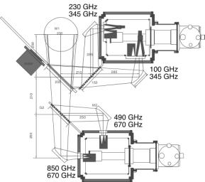
Fig. 6 Schematic view of LMSA prototype receiver system.
This system will be tested on the prototype 10m antenna in Chile. With a
rotating vane consisting of a flat mirror, a polarization grid, and a through
port, two observing frequencies can be flexibly selected.
C. Photonic LO System using photodiodes
To date, heterodyne detectors based on SIS junctions have used local oscillators (LO’s) consisting of frequency multipliers and diode oscillators. An alternative LO system is photonic LO sources, that is, photodiode or photomixer which generates the difference frequency of two laser diodes by optical heterodyne conversion. Photonic LO may offer reduced mechanical complexity and improve frequency coverage especially at submillimeter wavelength. Several types of photonic LO (or laser heterodyne systems) are proposed and tested so far. One of the most promising photonic LO sources in near future is an InP-InGaAs uni-traveling-carrier (UTC) photodiode developed by Ishibashi et al. [9, 10]. The output power of this source is expected to be about 1 mW at 150 GHz from measurements using laser diode at 1.55 mm.
The other one is low-temperature-grown (LTG) GaAs developed by Matsuura et al. [11]. The output power of 0.1 mW was obtained at 800 GHz in this source by using laser diodes at 0.85 micron and this photomixer LO was used for the 630 GHz heterodyn receiver using niobium SIS junction [12].
The development of sub-mm photonic LO is planned by NRO in collaboration with NTT and National Radio Astronomy Observatory (NRAO). The key issues are 1) the evaluation of currently available UTC photodiodes, 2) the new development of faster UTC photodiode, 3) the design of laser sources and LO system, and (4) performance test with combining the photonic LO system with SIS receivers.
D. Wideband Digital Spectro-correlators
There are three technical requirements for the correlator system in LMSA/ALMA. One is a wider observing bandwidth for achieving very high sensitivity in observations of dust emission from protoplanetary disks or protogalaxies. The other two are high spectral (frequency) resolution for the detailed study of kinematics in such disks and star forming dense molecular cores and a number of correlations to handle a large number of cross-correlations produced by a number of antennas. There are basically two different types of digital correlators, so-called FX and XF, which are considered as a spectro-correlator for the LMSA or ALMA, in order to achieve such requirements.
FX type correlator performs Fourier transform (F) before cross-correlation (X). This correlator is thought to fit well to LMAS or ALMA (or future unified single array) which should handle a large number of correlations and simultaneously cover wide band with very high spectral resolution (that is, a huge number of spectral channels) [13]. The current specifications of the FX correlator for LMSA/ALMA are shown in Table 2; a bandwidth of more than 4 GHz, a number of spectral channels per correlation (baseline) of 128 x 1024, and correlations of more than 2016 (produced by 64 antennas).
The prototypes of the FX correlator and very high-speed sampler are now under development. The sampler is used for the analog to digital conversion of IF signal before Fourier transform, and one of key components for achieving wide observing bandwidth. The specifications of the prototype sampler and FX correlator are also listed in Table 2; the sampling rate is as high as 4 G sample/sec. (Gsps) and the prototype FX, therefore, has a observing bandwidth of 2GHz and a number of frequency channels, 128 x 103. The design study of the prototypes was mostly finished and the prototype correlator and sampler will be constructed and evaluated within two years from now.
Table 2 Specifications of LMSA Correlators
Prototype LMSA
Correlator Type FX FX
Num. of Sampling Bit 2bit 2-3 bit
Num. of Correlation 1 > 2016
Bandwidth 2 GHz 4 GHz
Num. of Correlation Bit 2 bit 2-3 bit
Frequency Channels 128x103 128x103
(for each baseline)
Spectral Resolution 16 kHz 32 kHz
III. References
[1] Ohta, K., Yamada, T., Nakanishi, K., Kohno, K., Akiyama, M., and Kawabe, R., “Detection of molecular gas in the quasar BR1202–0725 at redshift z=4.69,” Nature, 382, pp. 426–428, 1996
[2] Kawabe, R., Ishiguro, M., Omodaka, T., Kitamura, Y., and Miyama, S., “Discovery of a rotating protoplanetary gas disk around the young star GG Tauri,” Astrophys. J., 404, pp. L63–L66, 1993
[3] Ishiguro, M., and LMSA working group, “Japanese Large Millimeter and Submillimeter Array,” Proc. SPIE, 3357, pp. 244–253, 1998
[4] http://www.nro.nao.ac.jp/~lmsa/
[5] http://www.mma.nrao.edu/
[6] http://pupis.ls.eso.org/lsa/lsahome.html
[7] Matsushita, S., Matsuo, H., Pardo, J. R., and Radford, S. J. E., “FTS measurements of submillimeter-wave atmospheric opacity at Pampa la Bola. II. Supra-terahertz windows and model fitting,” Publ. Astron. Soc. Japan, in press, 1999
[8] Shi, S. C., Noguchi, T., and Inatani, J., “Development of a 500-GHz band SIS mixer,” IEEE Trans. Applied Superconductivity, vol. 7, No. pp. 2587-2590, 1997
[9] Shimizu, N., Watanabe, N., Furuta, T., and Ishibashi, T., “InP-InGaAs Uni-traveling-Carrier Photodiode With Improved 3-dB Bandwidth of Over 150 GHz,” IEEE, Photonics Technology Letters, Vol. 10, No. 3, pp. 412-415, 1998
[10] Shimizu, N., Watanabe, N., Furuta, T., and Ishibashi, T., “Improved Response of Uni-traveling-Carrie Photodiodes by Carrier Injectio,” Jpn. J. Appl. Phys., 37, pp1424-1426, 1998
[11] Matsuura, S., Blake, G., Wyss, R., Pearson J., Kadow, C., Jackson, A., and Grossard, A., “ A Travering-wave THz photomixer based on angle-tuned phase matching,” App. Phy. Lett., vol. 74, no. 19, pp. 2872–2874, 1999
[12] Verghese, S., Dueit, E., McIntosh, K., Duffy, S., Calawa, S., Tong, C., Kimberk, R., and Blundell, R., “A Photomixer Local Oscillator for a 630-GHz Heterodyne Receiver,” IEEE, Microwave and Guided Wave Letters, vol. 9, no. 6, pp245-pp248, 1999
[13] Chikada et al. , “A 6 x 320-MHz FFT Spectrum Analyzer for Radio Astronomy,” Proc. .IEEE, vol. 75, no. 9, pp1203-1210, 1987